> ## Documentation Index
> Fetch the complete documentation index at: https://www.latitude.sh/docs/llms.txt
> Use this file to discover all available pages before exploring further.
# Private networks
> Private networking allows you to group servers within the same location, enabling private communication between them
Latitude.sh servers are configured with a public and a private interface on a Layer 3 network topology by default. With private networking, you can switch to a Layer 2 topology, allowing for L2 traffic between two or more instances.
This applies to both bare-metal servers and the virtual machines running on them: a VM can attach to the same private network and reach the bare-metal hosts — and other VMs — over Layer 2, using the same VLAN and subnet.
Layer 2 packets don't go through the network layer, and traffic is not filtered in any way. Latitude.sh does not charge for traffic from private networks, either inbound or outbound.
## Benefits & use cases
Private networking provides a myriad of benefits, with the most important ones being:
* Traffic doesn't go through the public internet, enhancing security.
* Private network traffic doesn't count against your bandwidth quota.
This feature is especially useful when you don't want or need traffic from specific servers going through the public internet. Common use cases include:
* Connecting a database server to a web application privately.
* Managing internal services like DHCP.
* Setting up Kubernetes clusters with direct node communication.
* Letting virtual machines communicate privately with the bare-metal hosts they run on.
 ## Setup
### Step 1: Create a VLAN
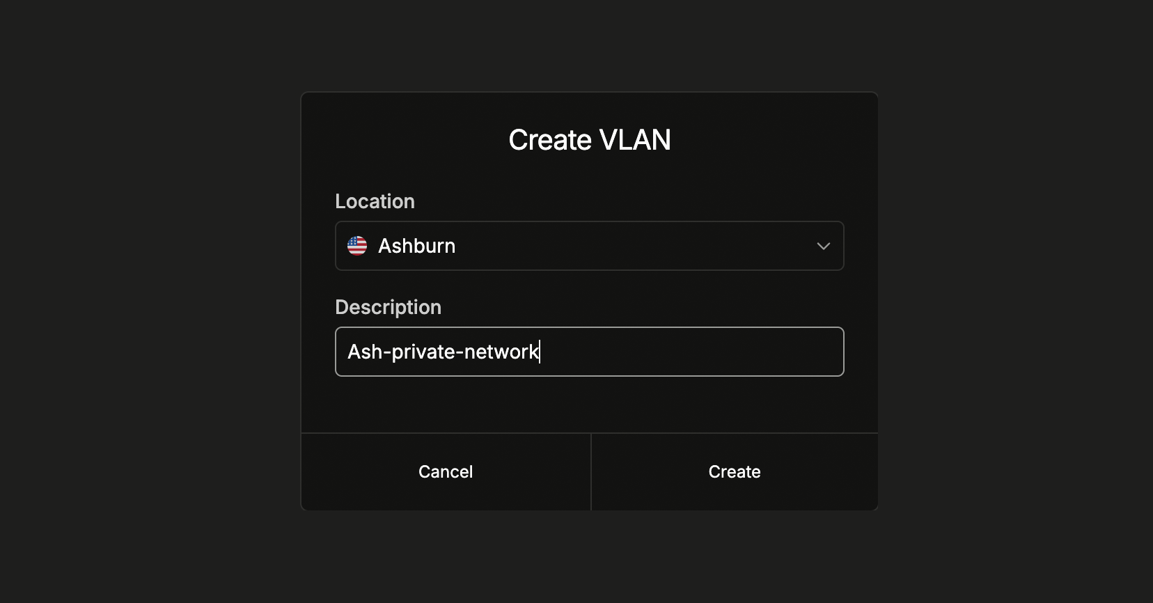
The first step is to create a Virtual Network — commonly referred to as VLAN.
[Log in to the dashboard](https://www.latitude.sh/dashboard), select a
project, navigate to **Networking → Private networks** in the sidebar menu,
and click **Create VLAN**. Select the location and add a description to help
you identify what the VLAN is used for.
Use the [/virtual\_networks](https://www.latitude.sh/docs/api-reference/create-virtual-network) endpoint to create a VLAN.
### Step 2: Assign servers
After creating the VLAN, assign at least two servers to allow the server's private IPs to communicate.
## Setup
### Step 1: Create a VLAN
The first step is to create a Virtual Network — commonly referred to as VLAN.
[Log in to the dashboard](https://www.latitude.sh/dashboard), select a
project, navigate to **Networking → Private networks** in the sidebar menu,
and click **Create VLAN**. Select the location and add a description to help
you identify what the VLAN is used for.
Use the [/virtual\_networks](https://www.latitude.sh/docs/api-reference/create-virtual-network) endpoint to create a VLAN.
### Step 2: Assign servers
After creating the VLAN, assign at least two servers to allow the server's private IPs to communicate.
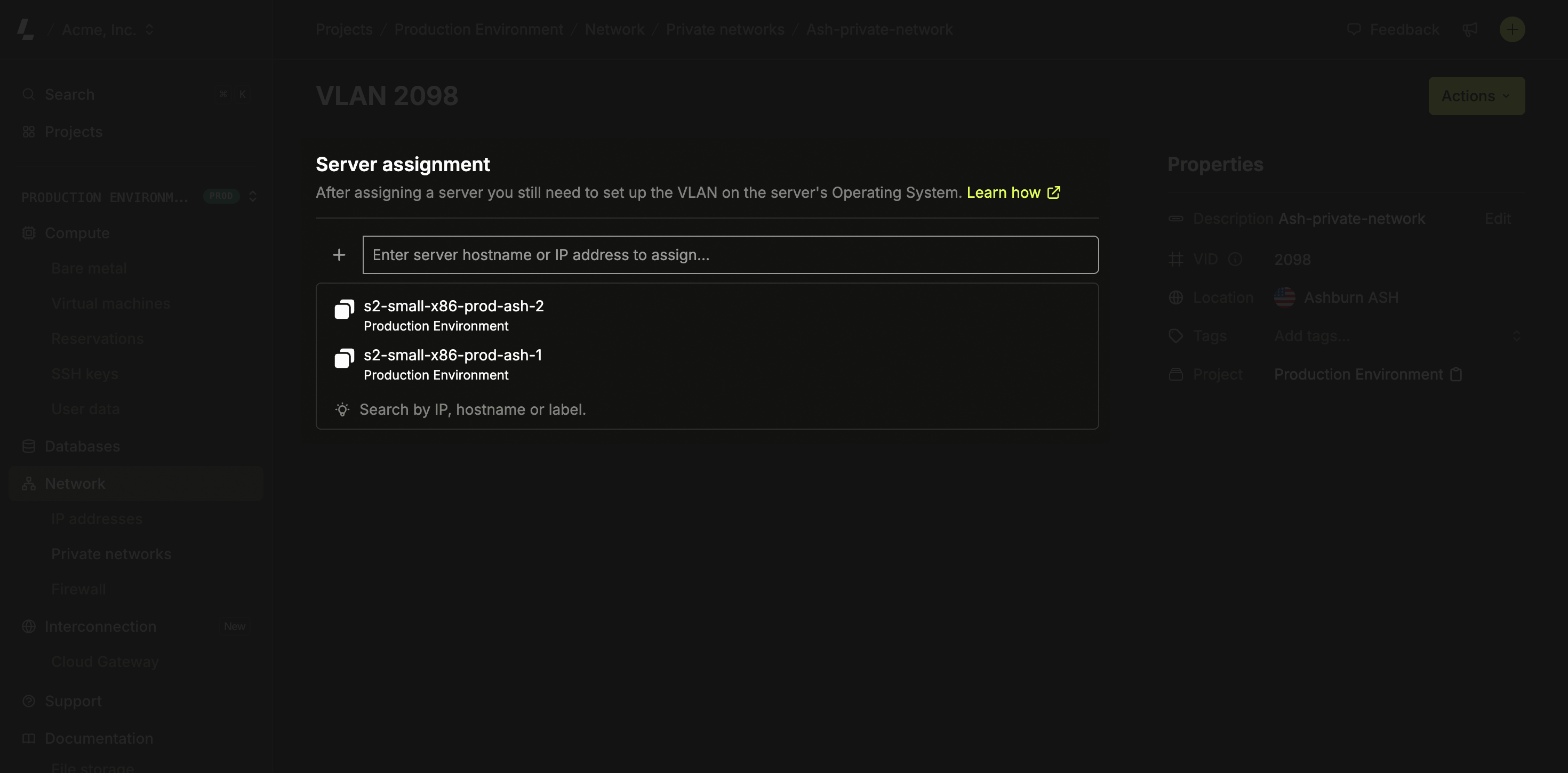 Go to the Virtual Network you created and click **Assign**. Select the
server you'd like to assign - only servers from the facility the virtual
network was created in will be listed. Save and wait a few seconds while the
network is provisioned.
You assign **servers** to the VLAN here. Virtual machines join the same private network through the host they run on — attach a NIC to the VLAN on the host's private interface, then configure the guest as shown in **Step 3 → Virtual machines**.
### Step 3: Configure the OS
The network provisioning on Latitude.sh switches is handled automatically after you assign your first server to a VLAN. Latitude.sh has no access to your servers, an additional step is required, and you need to configure the VLAN on your Operating System.
```bash theme={null}
sudo modprobe 8021q
sudo apt install vlan
```
Change the Netplan configuration file in `/etc/netplan/50-cloud-init.yaml` and add the configuration below to the end of the file.
* Replace `{{VID}}` with the **VID** value from the VLAN you created.
* Replace `10.8.0.1` with a private address of your choice. This address becomes the private IP of the server within the VLAN. It can be anything you want, but each server in the same VLAN needs a different IP.
* Replace `eno2` with the correct interface name. For servers with bonded interfaces, use bond0.
```yaml theme={null}
vlans:
vlan.{{VID}}:
id: {{ VID }}
link: eno2
addresses: [10.8.0.1/24]
```
The `vlans` section should be at the same indentation level as the `ethernets` key.
Due to eventual changes in Netplan versions, to use [Cloud Gateway](/networking/cloud-gateway), you need to define a default route to ensure proper network routing.
You can do that by adding the following routes section under the vlans key:
```yaml theme={null}
routes:
- to: 10.8.0.0/16
via: 192.168.0.1
```
* Replace `10.8.0.0/16` with the network prefix you want to reach through eno2.
* Replace `192.168.0.1` with the gateway IP address for your network (typically the first IP of your subnet).
```shell theme={null}
sudo netplan apply
```
This configuration is persistent, you don't need to do anything else.
When the server runs virtual machines, the host's virtual bridge applies the VLAN tag for the guest. **Do not** tag the VLAN again inside the guest — a `vlans:` block in the VM double-tags the frames (QinQ), the switch drops them, ARP never resolves, and you'll see `Destination Host Unreachable`.
Never copy the Ubuntu tag-in-guest pattern (the `vlans:` block) into a VM. On bare metal the guest tags the VLAN; on a VM the host bridge already does. Inside the guest, the private NIC must be a plain, **untagged** interface.
On the virtualization host, attach a **second network interface** to the VM, connected to a VLAN-backed network whose VLAN ID matches the VLAN you created on Latitude.sh. That network's uplink must be the server's **private NIC** (`eno2`).
* The VLAN ID **must match** the bare-metal VLAN's **VID**.
* This is configured on the virtualization host, not in the guest OS.
Inside the VM, edit `/etc/netplan/50-cloud-init.yaml` and add the second NIC as a new entry **inside the existing `ethernets:` block** as a plain interface. **Do not** add a `vlans:` block, and do not create a second `ethernets:` key — YAML silently keeps only one of them, wiping the primary NIC's config.
```yaml theme={null}
# add inside the existing ethernets: block, alongside the primary NIC
enp2s0:
addresses: [10.8.0.2/24]
```
* Replace `enp2s0` with the second NIC's name inside the guest (run `ip a` to find it).
* Replace `10.8.0.2/24` with a private address in the **same subnet and prefix** as the bare-metal servers on this VLAN. Each host in the VLAN needs a unique IP.
* Do **not** set a gateway on this interface — keep the default route on the public NIC (`enp1s0`) only.
Remove any leftover `vlans:` / `vlan.{{VID}}` stanza and any stray addresses on unrelated subnets before applying. Use **static** IPs on every NIC — do not run DHCP on more than one interface, or the DHCP clients race over the default route and cause intermittent packet loss.
```shell theme={null}
sudo netplan generate
sudo netplan apply
```
Running `netplan generate` first surfaces silent errors before you apply. Then verify Layer 2 reachability from the VM to a bare-metal host on the same VLAN:
```shell theme={null}
arping -I enp2s0
sudo arp-scan --interface=enp2s0 10.8.0.0/24
```
A reply confirms the fix. `Destination Host Unreachable` means ARP failed — the NIC is still double-tagged, or the VLAN ID, NIC, or subnet don't match the bare-metal side.
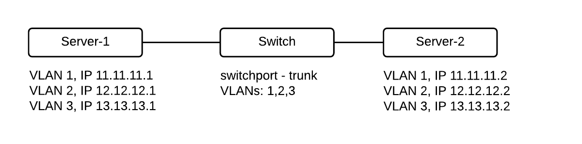
This will show you how to set up multiple VLANs on a single network interface when using Windows Server 2012 or later.
Go to the Virtual Network you created and click **Assign**. Select the
server you'd like to assign - only servers from the facility the virtual
network was created in will be listed. Save and wait a few seconds while the
network is provisioned.
You assign **servers** to the VLAN here. Virtual machines join the same private network through the host they run on — attach a NIC to the VLAN on the host's private interface, then configure the guest as shown in **Step 3 → Virtual machines**.
### Step 3: Configure the OS
The network provisioning on Latitude.sh switches is handled automatically after you assign your first server to a VLAN. Latitude.sh has no access to your servers, an additional step is required, and you need to configure the VLAN on your Operating System.
```bash theme={null}
sudo modprobe 8021q
sudo apt install vlan
```
Change the Netplan configuration file in `/etc/netplan/50-cloud-init.yaml` and add the configuration below to the end of the file.
* Replace `{{VID}}` with the **VID** value from the VLAN you created.
* Replace `10.8.0.1` with a private address of your choice. This address becomes the private IP of the server within the VLAN. It can be anything you want, but each server in the same VLAN needs a different IP.
* Replace `eno2` with the correct interface name. For servers with bonded interfaces, use bond0.
```yaml theme={null}
vlans:
vlan.{{VID}}:
id: {{ VID }}
link: eno2
addresses: [10.8.0.1/24]
```
The `vlans` section should be at the same indentation level as the `ethernets` key.
Due to eventual changes in Netplan versions, to use [Cloud Gateway](/networking/cloud-gateway), you need to define a default route to ensure proper network routing.
You can do that by adding the following routes section under the vlans key:
```yaml theme={null}
routes:
- to: 10.8.0.0/16
via: 192.168.0.1
```
* Replace `10.8.0.0/16` with the network prefix you want to reach through eno2.
* Replace `192.168.0.1` with the gateway IP address for your network (typically the first IP of your subnet).
```shell theme={null}
sudo netplan apply
```
This configuration is persistent, you don't need to do anything else.
When the server runs virtual machines, the host's virtual bridge applies the VLAN tag for the guest. **Do not** tag the VLAN again inside the guest — a `vlans:` block in the VM double-tags the frames (QinQ), the switch drops them, ARP never resolves, and you'll see `Destination Host Unreachable`.
Never copy the Ubuntu tag-in-guest pattern (the `vlans:` block) into a VM. On bare metal the guest tags the VLAN; on a VM the host bridge already does. Inside the guest, the private NIC must be a plain, **untagged** interface.
On the virtualization host, attach a **second network interface** to the VM, connected to a VLAN-backed network whose VLAN ID matches the VLAN you created on Latitude.sh. That network's uplink must be the server's **private NIC** (`eno2`).
* The VLAN ID **must match** the bare-metal VLAN's **VID**.
* This is configured on the virtualization host, not in the guest OS.
Inside the VM, edit `/etc/netplan/50-cloud-init.yaml` and add the second NIC as a new entry **inside the existing `ethernets:` block** as a plain interface. **Do not** add a `vlans:` block, and do not create a second `ethernets:` key — YAML silently keeps only one of them, wiping the primary NIC's config.
```yaml theme={null}
# add inside the existing ethernets: block, alongside the primary NIC
enp2s0:
addresses: [10.8.0.2/24]
```
* Replace `enp2s0` with the second NIC's name inside the guest (run `ip a` to find it).
* Replace `10.8.0.2/24` with a private address in the **same subnet and prefix** as the bare-metal servers on this VLAN. Each host in the VLAN needs a unique IP.
* Do **not** set a gateway on this interface — keep the default route on the public NIC (`enp1s0`) only.
Remove any leftover `vlans:` / `vlan.{{VID}}` stanza and any stray addresses on unrelated subnets before applying. Use **static** IPs on every NIC — do not run DHCP on more than one interface, or the DHCP clients race over the default route and cause intermittent packet loss.
```shell theme={null}
sudo netplan generate
sudo netplan apply
```
Running `netplan generate` first surfaces silent errors before you apply. Then verify Layer 2 reachability from the VM to a bare-metal host on the same VLAN:
```shell theme={null}
arping -I enp2s0
sudo arp-scan --interface=enp2s0 10.8.0.0/24
```
A reply confirms the fix. `Destination Host Unreachable` means ARP failed — the NIC is still double-tagged, or the VLAN ID, NIC, or subnet don't match the bare-metal side.
This will show you how to set up multiple VLANs on a single network interface when using Windows Server 2012 or later.
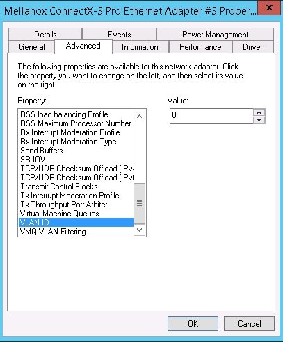
 1. If you want to configure a single VLAN in the interface, go to **Network Connections > Properties > Advanced tab > Select the VLAN ID** field and add the desired value.
If you want multiple VLANs in the same interface, make sure that the property **VLAN ID is set to 0** - otherwise, it will not work.
1. If you want to configure a single VLAN in the interface, go to **Network Connections > Properties > Advanced tab > Select the VLAN ID** field and add the desired value.
If you want multiple VLANs in the same interface, make sure that the property **VLAN ID is set to 0** - otherwise, it will not work.
 2. Access your server's IPMI via the [Remote access](/servers/remote-access) feature.
3. On your IPMI interface go to **Server Manager > Local server** and click on **NIC Teaming**.
2. Access your server's IPMI via the [Remote access](/servers/remote-access) feature.
3. On your IPMI interface go to **Server Manager > Local server** and click on **NIC Teaming**.
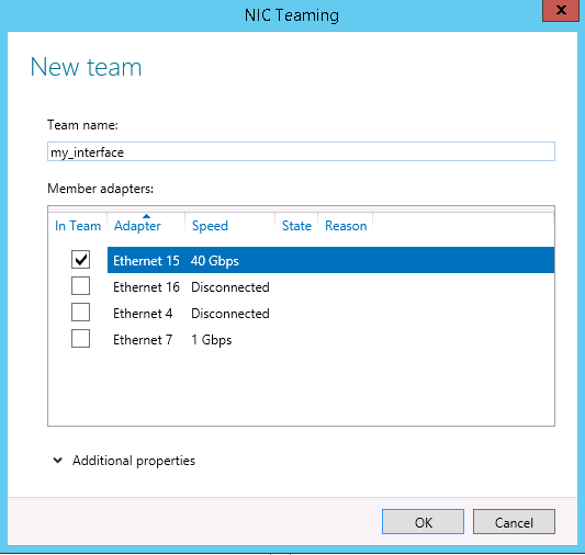
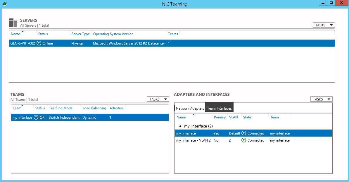
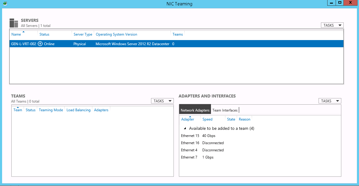 4. Create a new Team with a single interface by going to **Teams > Tasks > New Team**. Select the desired interface (e.g. 40GbE) and give it a name. Once you create the Team, your IP configuration will be cleaned and your server's internet connection will be lost until the end of the process. **Select your secondary interface for the private VLAN**.
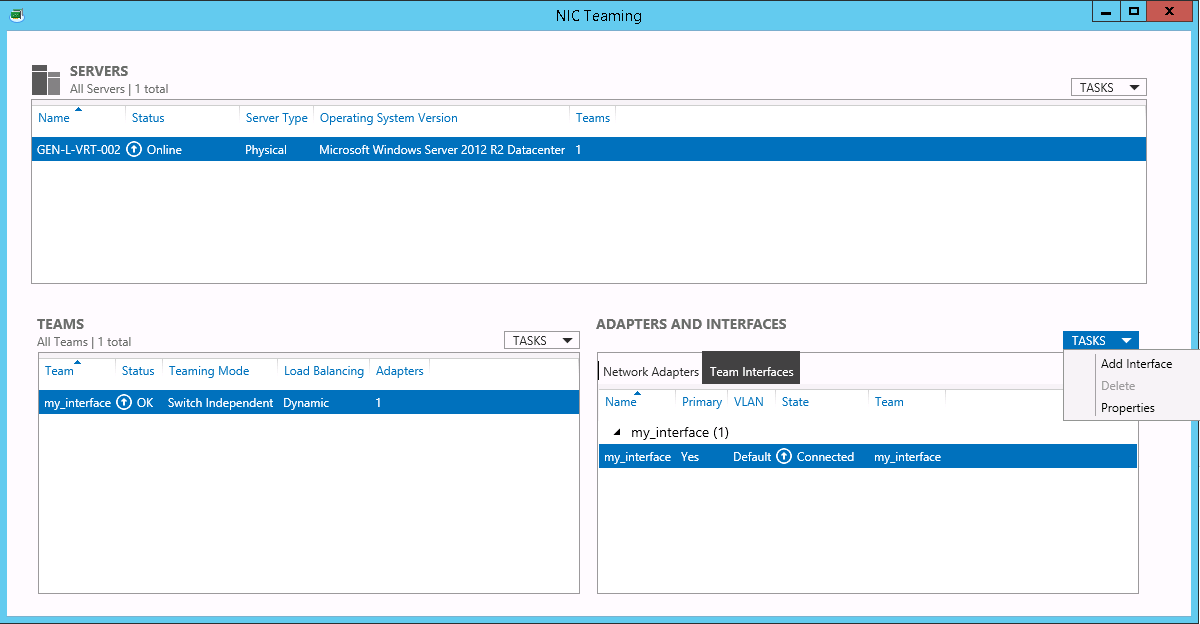
 5. Go to **Adapter and Interfaces** and click on **TASKS > Add Interface**. The first interface needs to have the **VLAN ID 0 (zero)** or **Default**.
 6. Configure the specific VLAN and click OK. The VLAN ID that you need to configure is the same displayed on your dashboard.
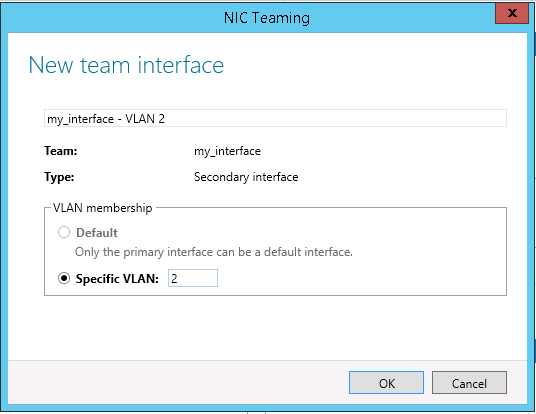 7. To add another VLAN interface on the same port, repeat step #4.
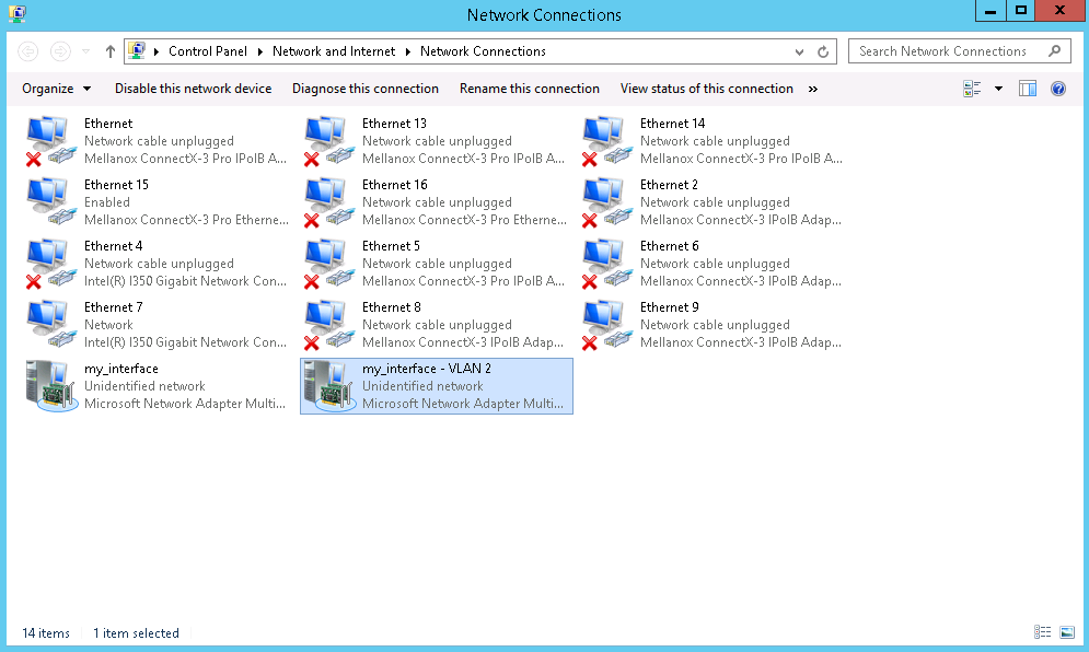
 8. To assign an IP address to the new interface, click on **Network Connections**, and find the VLAN interface you have just added. Then, configure the IP similarly to any other interface. You need to configure the VLAN 0 with your public IP.
You can configure any IP address in your private VLAN (e.g.: 10.10.10.1/24) and you don't need to configure a Gateway in the private interfaces. Gateway information is only mandatory for ' Public' Interfaces.
8. To assign an IP address to the new interface, click on **Network Connections**, and find the VLAN interface you have just added. Then, configure the IP similarly to any other interface. You need to configure the VLAN 0 with your public IP.
You can configure any IP address in your private VLAN (e.g.: 10.10.10.1/24) and you don't need to configure a Gateway in the private interfaces. Gateway information is only mandatory for ' Public' Interfaces.
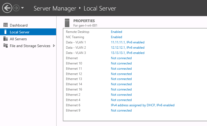
 Let's say you created three VLAN interfaces (VLANs 1,2,3) on the teaming interface and add three IP addresses, here is what you should see on the Server Manager window:
 **Troubleshooting**
* If you try to configure multiple VLANs, make sure that the value of the VLAN ID field in the properties Advanced tab is equal to 0.
* Do not configure the primary virtual interface with the VLAN ID, as it needs to be on its default configuration (VLAN ID 0). When the port configuration is set up to native VLAN, do not change this VLAN configuration.
In Red Hat Enterprise Linux and Centos 7, the 8021q module is loaded by default. If necessary, you can make sure that the module is loaded by issuing the following command as root:
```shell theme={null}
modprobe --first-time 8021q
modprobe: ERROR: could not insert '8021q': Module already in kernel
```
To display information about the module, issue the following command:
```shell theme={null}
modinfo 8021q
```
See the `modprobe(8)` man page for more command options.
## Additional Resources
Configure the parent interface in `/etc/sysconfig/network-scripts/ifcfg-eno2`.
```bash theme={null}
DEVICE=eno2
TYPE=Ethernet
BOOTPROTO=none
ONBOOT=yes
```
Set the VLAN interface configuration in the `/etc/sysconfig/network-scripts/ directory`. The configuration file name should be the parent interface plus a `.` character followed by the VLAN ID number. For example, if the VLAN ID is 192, and the parent interface is eth0, then the configuration file name should be `ifcfg-eno2.192`:
```bash theme={null}
DEVICE=eno2.192
BOOTPROTO=none
ONBOOT=yes
IPADDR=192.168.1.1
PREFIX=24
NETWORK=192.168.1.0
VLAN=yes
```
If there is a need to configure a second VLAN, with, for example, VLAN ID 193, on the same interface, eno2, add a new file with the name `eno2.193` with the VLAN configuration details. Restart the networking service in order for the changes to take effect. As `root` issue the following command:
```shell theme={null}
systemctl restart network
```
**Troubleshooting**
* If you try to configure multiple VLANs, make sure that the value of the VLAN ID field in the properties Advanced tab is equal to 0.
* Do not configure the primary virtual interface with the VLAN ID, as it needs to be on its default configuration (VLAN ID 0). When the port configuration is set up to native VLAN, do not change this VLAN configuration.
In Red Hat Enterprise Linux and Centos 7, the 8021q module is loaded by default. If necessary, you can make sure that the module is loaded by issuing the following command as root:
```shell theme={null}
modprobe --first-time 8021q
modprobe: ERROR: could not insert '8021q': Module already in kernel
```
To display information about the module, issue the following command:
```shell theme={null}
modinfo 8021q
```
See the `modprobe(8)` man page for more command options.
## Additional Resources
Configure the parent interface in `/etc/sysconfig/network-scripts/ifcfg-eno2`.
```bash theme={null}
DEVICE=eno2
TYPE=Ethernet
BOOTPROTO=none
ONBOOT=yes
```
Set the VLAN interface configuration in the `/etc/sysconfig/network-scripts/ directory`. The configuration file name should be the parent interface plus a `.` character followed by the VLAN ID number. For example, if the VLAN ID is 192, and the parent interface is eth0, then the configuration file name should be `ifcfg-eno2.192`:
```bash theme={null}
DEVICE=eno2.192
BOOTPROTO=none
ONBOOT=yes
IPADDR=192.168.1.1
PREFIX=24
NETWORK=192.168.1.0
VLAN=yes
```
If there is a need to configure a second VLAN, with, for example, VLAN ID 193, on the same interface, eno2, add a new file with the name `eno2.193` with the VLAN configuration details. Restart the networking service in order for the changes to take effect. As `root` issue the following command:
```shell theme={null}
systemctl restart network
```